Stairway to heaven
- Intro
- Centre of mass
- Two- and three-dimensional situations
- Uniform lamina shapes
- Composite shapes
- Toppling & the centre of mass
- Back to the stacked blocks
- Final remarks
Intro
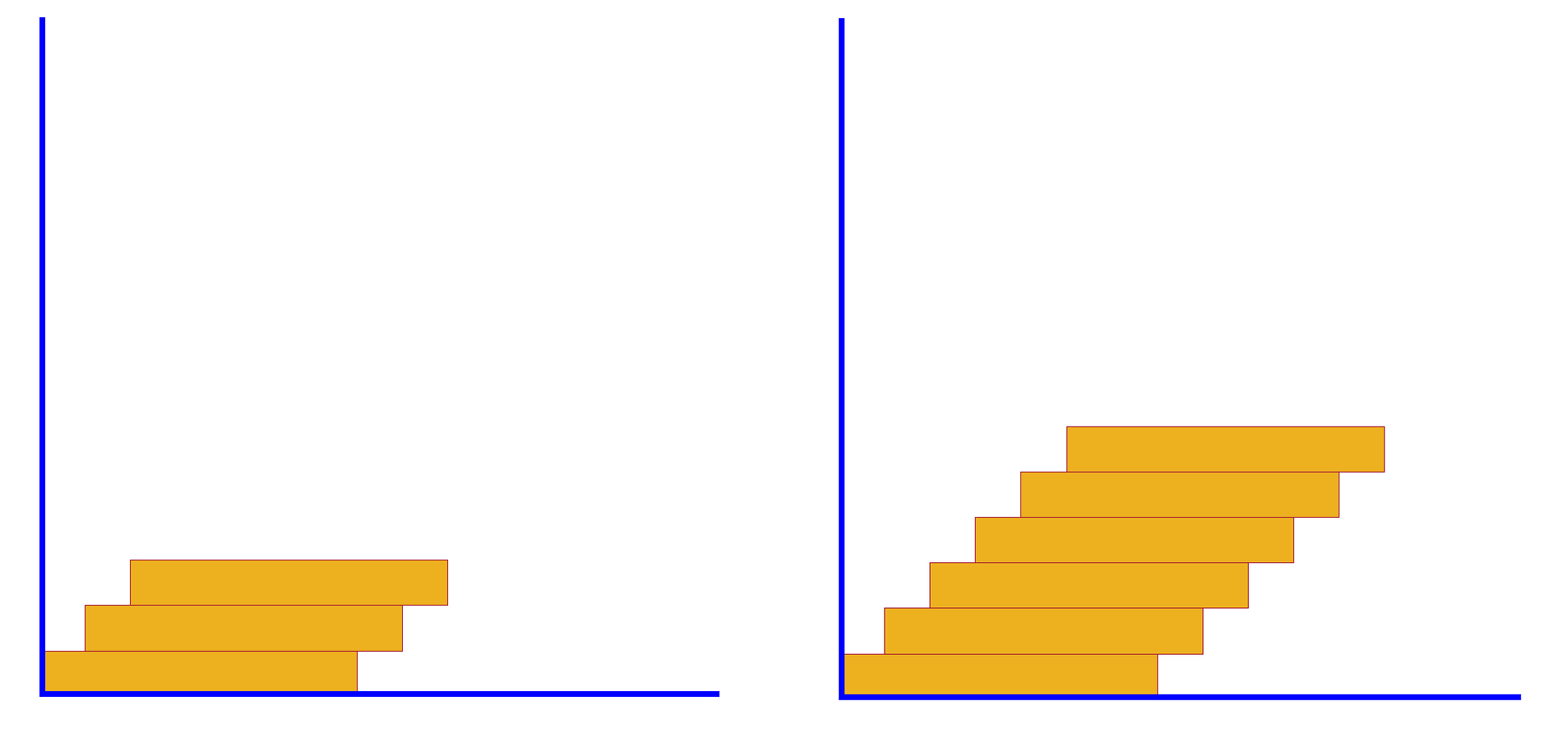
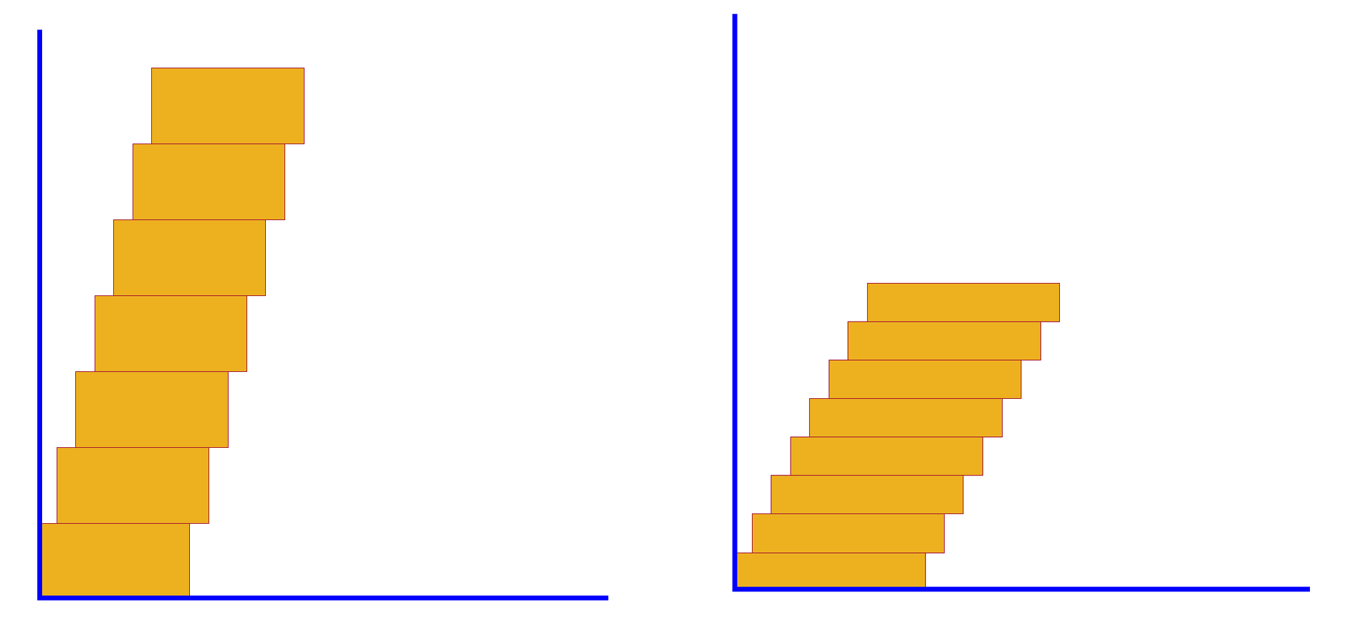
Consider a set of uniform wooden bricks that are glued together as shown in the diagrams included below. The bricks are identical, with each one at a certain distance to the right of the one immediately below it. The question is: how many bricks is it possible to assemble in this way without them tipping over?
To be concrete, assume that the length of each brick is $20$ cm and its height is $5$ cm. The amount by which they are offset to the right is $5$ cm. What is the maximum number of blocks that answer the previous question?
Assuming again the same dimensions for the bricks as stated above, but now the distance by which they are offset is $0.5$ cm, what is the maximum height possible for such an assembly of bricks without them tipping over?
Same question as above, but now the offset distance is $2$ cm.
To answer these questions we need some knowledge about the so-called centre of mass (also known as the centre of gravity).
Centre of mass
Let’s start with the one-dimensional case; in particular, we will look at a system of $N\geq{2}$ masses attached to a light rod (in this context, a light rod is one whose weight can be disregarded). The centre of mass (or CM for short) of this system of material particles is a point situated on the rod about which the total weight of the system exerts no torque. If we suspend our hypothetical rod from its centre of mass, there would be no torque at the suspension (i.e., support) point. In other words, the rod with the attached masses would be balanced. It is instructive to first consider the case of just two masses, as in the sketch included below.

The locations of the two masses, $m_1$ and $m_2$, are indicated by the points $A_1$ and $A_2$, respectively. Relative to the arbitrary origin $O$ of a one-dimensional system of coordinates, the abscissae of these points are denoted by $x_1$ and $x_2$. Each mass is subjected to the force of gravity; at $A_1$ we have the weight $W_1=m_1g$, while at $A_2$, the weight is $W_2=m_2g$ ($g$ is the usual standard acceleration of gravity). Let $C$ be the location of the centre of mass (the quantity we are looking for). Its distance from $O$ is denoted by $\overline{x}$.
The equilibrium of moments about the centre of mass $C$ requires
\[W_1\cdot {A_1}C = W_2\cdot{A_2}C\quad\Longrightarrow\quad (m_1g)(\overline{x}-x_1)= (m_2g)(x_2-\overline{x}).\]Dividing both sides of the last equation by $g$, expanding the brackets on each side, and then making $\overline{x}$ the subject gives
\[\begin{aligned}[t] &m_1(\overline{x}-x_1) =m_2(x_2-\overline{x})\quad\Longrightarrow\quad m_1\overline{x}-m_1{x_1} = m_2{x_2}-m_2\overline{x}\\ &{}\\ &\qquad\Longrightarrow\quad (m_1+m_2)\overline{x} = m_1x_1+m_2x_2\\ &{}\\ &\qquad\qquad\Longrightarrow\quad\overline{x} = \dfrac{m_1x_1+m_2x_2}{m_1+m_2}. \end{aligned} \tag{1}\]Note that although $g$ was included in the calculations, it cancelled out. The answer depends only on the masses and their distances from the origin and not on the value of $g$. The origin of the system of coordinates was also arbitrary (we could have chosen $O=A_1$ to simplify the calculations, but this would have resulted in the loss of symmetry of the last equation in (1)).
For the general case of an arbitrary number of masses attached to a rod we have a similar formula.
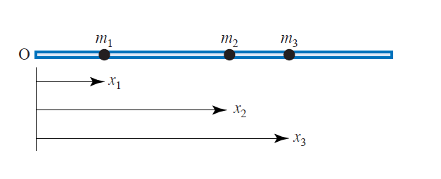
Consider a set of $N\geq{2}$ point masses $m_1$, $m_2$, $\dots$, $m_N$ attached to a rigid light rod (whose mass is neglected) at positions $x_1$, $x_2$, $\dots$, $x_N$ from one fixed point $O$ (see sketch below, where $N=3$).
The position $\overline{x}$ of the centre of mass relative to $O$ can be calculated by using the formula
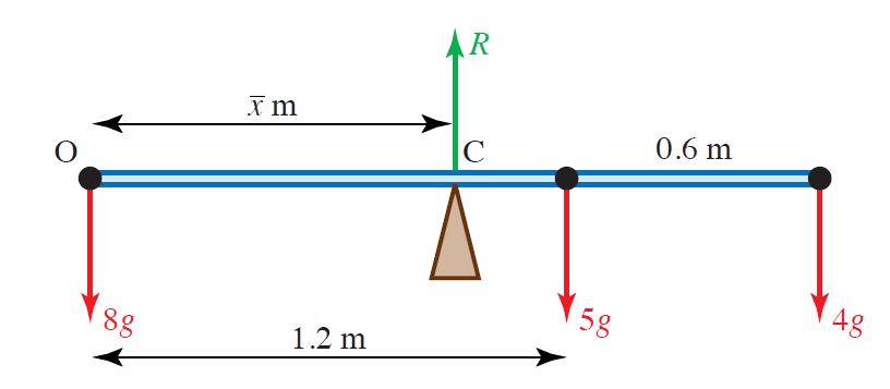
\[\overline{x} = \dfrac{m_1x_1+m_2x_2+\dots+m_Nx_N}{m_1+m_2+\dots+m_N}. \tag{2}\]Example: Consider a rigid light rod with three point masses attached to it as shown below. Find the distance of the centre of mass of this system from the end $O$.

Solution:
Suppose the centre of mass $C$ is situated at a distance $\overline{x}$ (in metres) from $O$. Using formula (2) we have
\[\overline{x}=\dfrac{(8)\times(0) + (5\times 1.2) + (4)\times (1.8)}{8 + 5 + 4} = \dfrac{13.2}{17}\simeq 0.776;\]hence, the centre of mass is $0.776$ metres from the end $O$ of the rod.
In our discussion of the CM above it was assumed that the rod was light and its weight was neglected in the calculations. If the rod is uniform and its mass is given, it can be treated as a point mass at its centre. Consider the following concrete example: we are asked to identify the CM of a rod of length $2$ metres and mass $5$ kg, with additional masses of $4$ kg and $6$ kg attached at each of its two ends. All we have to do is: (i) introduce a new point mass of $5$ kg at the centre of the rod; (ii) assume that the new system of three masses is attached to a light rod (i.e., we treat the new situation using the previously developed strategy). Refer to the sketch below (taking the origin at $A$, the answer is $\overline{x}=17/15$ metres from that point):

Two- and three-dimensional situations
If the discrete masses in a system are not in a straight line we need to give their positions as coordinates relative to some fixed axes. The coordinates of the centre of mass can then be found by using the same method as for the one-dimensional situation described above. However, this time formula (2) must be applied twice (once for the $x$-coordinates, and again for the $y$-coordinates). For easy reference we record the corresponding formulae below.
Consider a two-dimensional system of $N\geq{2}$ point masses $m_1$, $m_2$, $\dots$, $m_N$ located at positions $(x_1,y_1)$, $(x_2,y_2)$, $\dots$, $(x_N,y_N)$ as in the figure below (where $N=7$).
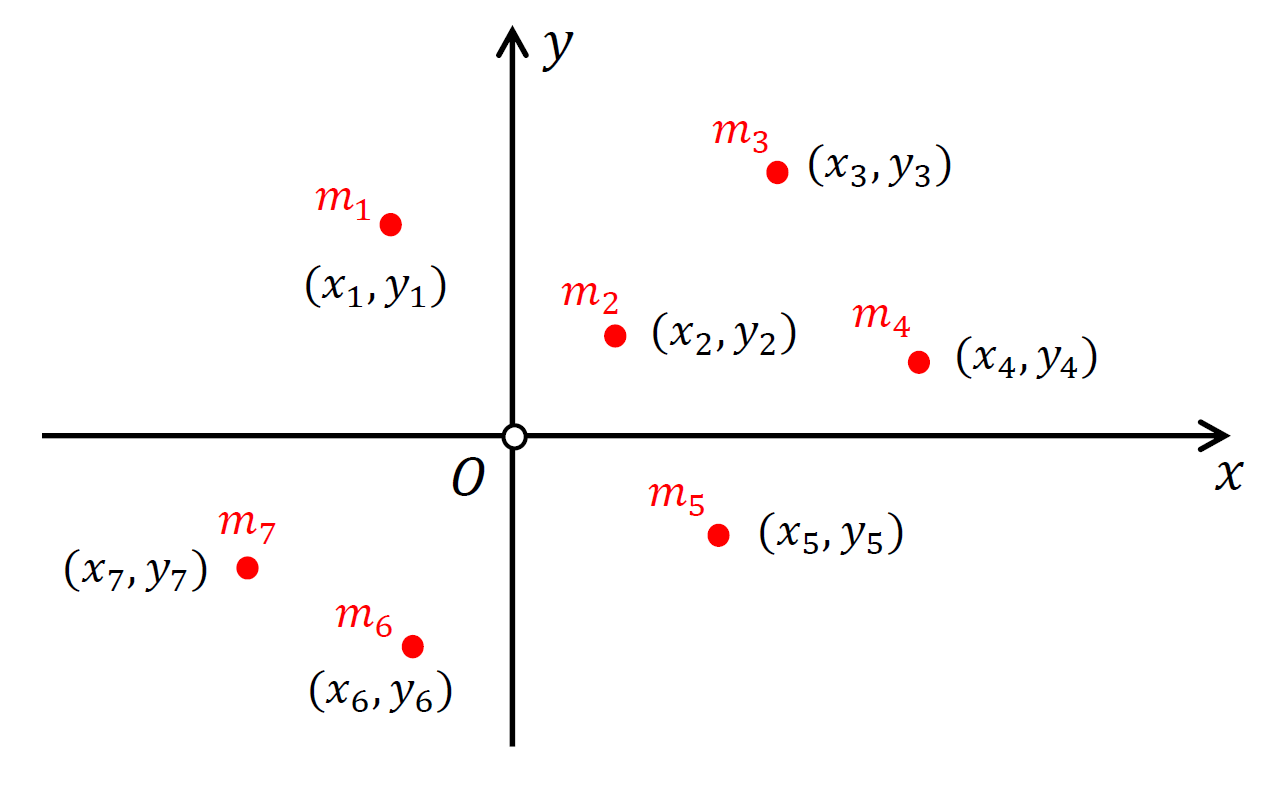
Then, the position of the centre of mass of this configuration, $(\overline{x},\overline{y})$, is given by
\[\begin{aligned}[t] &\overline{x} = \dfrac{m_1x_1+m_2x_2+\dots+m_Nx_N}{m_1+m_2+\dots+m_N}\\ &{}\\ &\overline{y} = \dfrac{m_1y_1+m_2y_2+\dots+m_Ny_N}{m_1+m_2+\dots+m_N}. \end{aligned} \tag{3}\]In three dimensions, each point will have an additional $z$-coordinate; this includes the CM, whose coordinates will be an ordered triple $(\overline{x}, \overline{y}, \overline{z})$. The formula for $\overline{z}$ will be similar to (3), except for the obvious changes (e.g., $x_i\to z_i$ with $i=1,2,\dots,N$).
The CM does not depend on the system of coordinates chosen (typically, if the axes and coordinates are not specified, it helps to choose the axes so that the calculations are simplified).
Uniform lamina shapes
By a lamina is meant an object which can be modelled as a plane region with no thickness. A uniform lamina has its mass distributed evenly throughout its area.
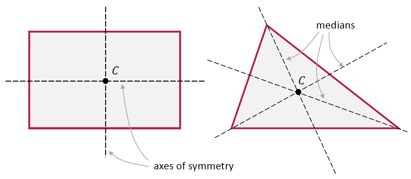
Any uniform lamina with an axis of symmetry has its mass evenly distributed on either side of the axis; Thus, the CM of that shape must lie on its axis of symmetry. For a lamina with more than one axis of symmetry, it follows that the CM of mass is located at the intersection of those axes; see sketch below.
For example, a uniform rectangular lamina has two lines of symmetry, each one joining the mid-points of a pair of opposite sides. The CM of this geometrical shape is at the point where the two lines meet (which is the same as the intersection point of its diagonals).
The CM of any uniform triangular lamina is at the intersection of the medians (these are lines that join a vertex to the mid-point of the opposite side). This point is called the centroid of the triangle. Note that the medians are not axes of symmetry of the triangle unless the triangle is equilateral; see sketch below.
Composite shapes
A uniform plane figure (i.e., a lamina) may consist of two or more of the standard uniform shapes mentioned in the previous section, which have been joined together to form a composite plane figure.
We can use the formulae (3), together with knowledge of the position of the CM of standard shapes, to find the CM of a composite lamina. The example included below clarifies how this is done in practice.
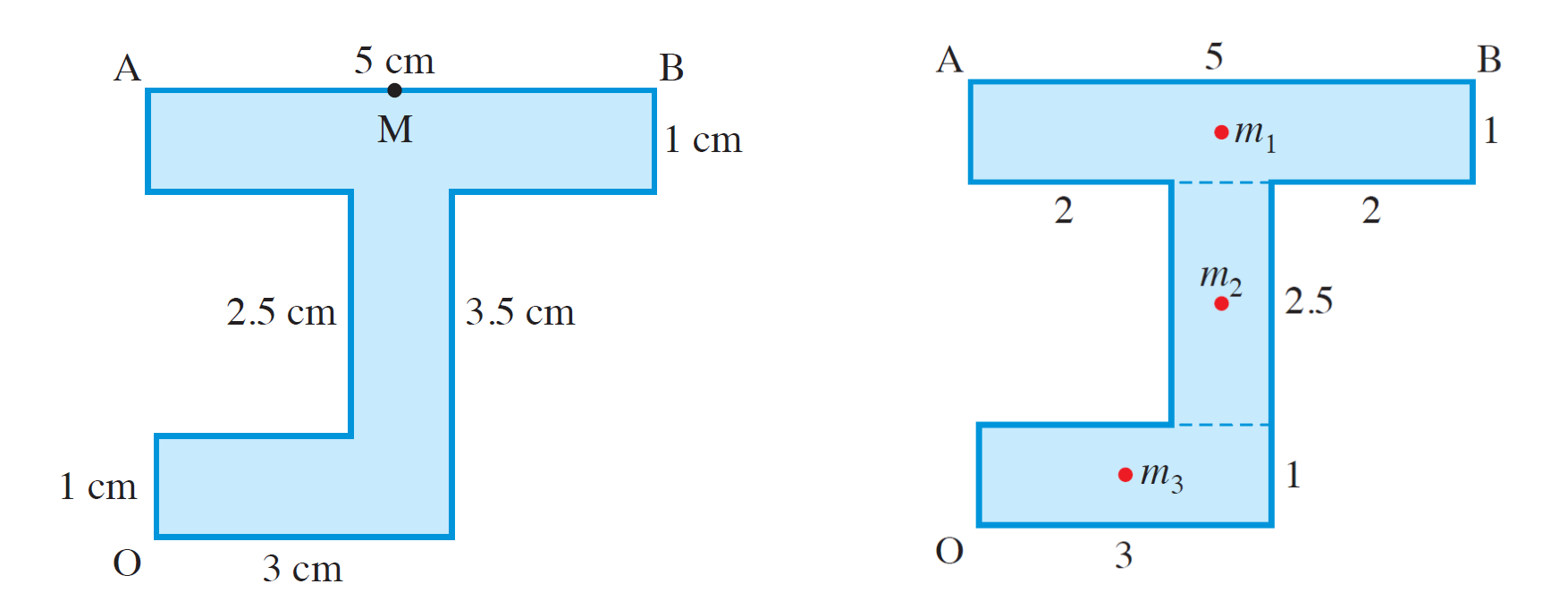
Example: Consider the lamina included in the left figure below. We are interested in finding its CM.
Solution:
The relatively complicated shape of the lamina can be split into three rectangles, as shown in the right figure above. The centres of mass of each of these rectangles is at their middle (indicated by the red circular markers).
We will model the original lamina as three point masses $m_1$, $m_2$, $m_3$, which are proportional to the areas of the rectangular shapes. Based on the dimensions given in the above figures, $m_1=5$, $m_2=2.5$, $m_3=3$ (in suitable units). The numerical values in these equations are the areas of the corresponding rectangles. The units in which we measure the masses are irrelevant because given the form of the two relations in (3), there will be a cancellation between the mass units used in the numerator and the denominator of each of those two fractions.
Applying the formulae (3):
\[\overline{x} = \dfrac{(5)\times(2.5) + (2.5)\times(2.5) + (3)\times(1.5)}{5+2.5+3} = \dfrac{23.25}{10.5}\simeq 2.2\quad\mbox{cm}.\]For the vertical coordinate:
\[\overline{y} = \dfrac{(5)\times(4) + (2.5)\times(2.25) + (3)\times(0.5)}{5+2.5+3} = \dfrac{27.25}{10.5}\simeq 2.6\quad\mbox{cm}.\]In conclusion, the centre of mass is at $(2.2, 2.6)$.
Toppling & the centre of mass
The location of the centre of mass is important for stability. The key rule in this context is the following: if we draw a line straight down from the CM of an object resting on a flat surface and it falls within the base of the object, then the object is in stable equilibrium (i.e., it will balance). The base of the object is its corresponding part that is in direct contact with the flat surface on which it rests. If the aforementioned line falls outside the base, the object is unstable. Examine the situations depicted in the figure below:
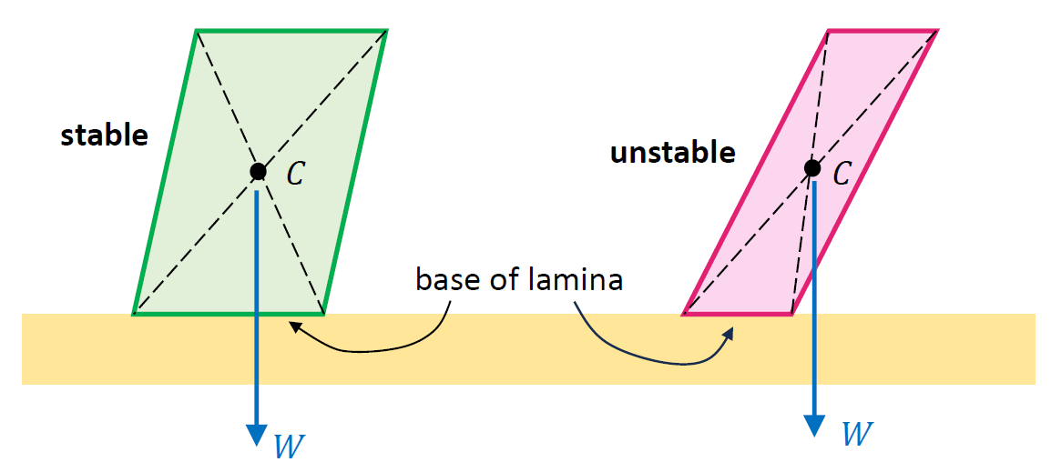
Shown in this diagram are two uniform laminae in the shape of a parallelogram. The CM of this type of object is given by the point where the two diagonals intersect each other. Note that in the first case the straight line from $C$ does fall within the base of the parallelogram, but this is no longer true in the situation seen on the right.
There are a number of implications of this simple rule. For example, you can lean over and touch your toes without falling over if your CM is above the area bounded by your feet. But if you try to do this while standing with your back right next to a wall, you’ll most likely find it impossible.
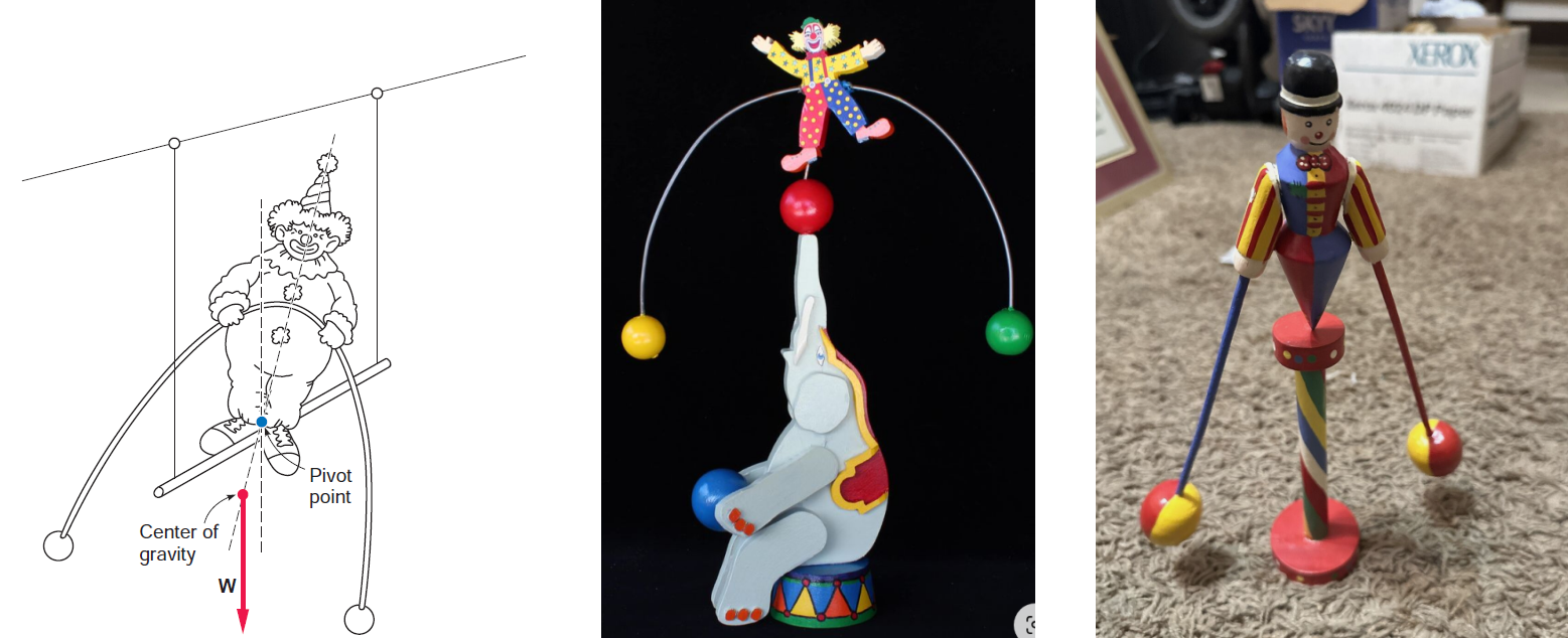
Also, you have perhaps noticed that some acrobats who practice tightrope walking carry a long flexible pole, like the ones seen in the pictures included below. This is a heavy, flexible structure that helps the acrobat lower his/her centre of mass. The flexibility of the pole is quite important; due to its weight, the pole droops, bringing the CM of the composite system ‘acrobat’ + ‘pole’ closer to the rope (or cable). The pole also serves to increase the rotational inertia of the same system (but that’s a story for another day… or post).

Balancing toys (which were once in vogue) rely on a strategic placement of the CM to produce unexpected & entertaining effects for kids; some examples can be seen in the sketch and photographs below. Take the example on the left – its secret to regaining its upright balance when disturbed? The centre of mass returns to the position directly below the pivot point, where the weight of the toy produces no torque.
Back to the stacked blocks
After this brief detour we are now ready to return to the problem stated at the beginning of this post. It is clear that the stacked blocks form a composite shape whose centre of mass will have to be calculated by using the methods explained above. While the wooden blocks are in fact three-dimensional, we can make the simplifying assumption that we are dealing with a set of identical rectangular laminae. To facilitate the calculations, some new notations are introduced; $L$ denotes the length of each rectangle (i.e., the horizontal dimension), $H$ represents the corresponding height (i.e., the vertical dimension), while $d$ is the offset distance mentioned previously (there is no need to exclude the case $L < H$). The sketch below provides further details.
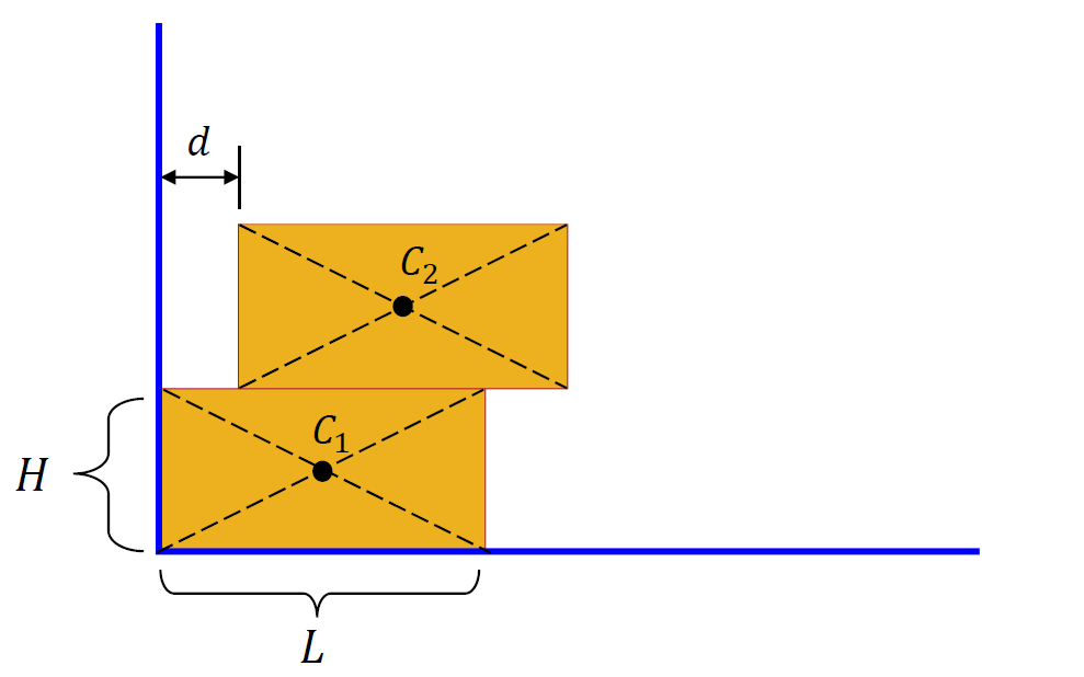
The blocks will be labelled in increasing order, from the bottom to the top of the stack: block $1$, block $2$, and so on (up to block $N$ – the one at the very top); their centres of mass will be identified as $C_j$, with $j=1,2,\dots,N$.
With these conventions in mind, the coordinates of the centres of mass will be as follows
\[\begin{aligned}[t] &C_1:\quad x_1 = \dfrac{L}{2},\qquad y_1=\dfrac{H}{2}\\ &{}\\ &C_2:\quad x_2 = d+\frac{L}{2}\,\qquad y_2 = H+\dfrac{H}{2}=\dfrac{3H}{2}\\ &{}\\ &C_3:\quad x_3 = 2d+\frac{L}{2}\,\qquad y_3 = 2H+\dfrac{H}{2}=\dfrac{5H}{2}\\ &{}\\ &C_4:\quad x_4 = 3d+\frac{L}{2}\,\qquad y_4 = 3H+\dfrac{H}{2}=\dfrac{7H}{2}\\ &{}\\ & \dots\dots\\ &{}\\ &C_N: \quad x_N = (N-1)d+\frac{L}{2}\,\qquad y_N = (N-1)H+\dfrac{H}{2}=\dfrac{(2N-1)H}{2}. \end{aligned}\]Use of formulae (3) gives the coordinates $(\overline{x},\overline{y})$ of the CM of the composite shape
\[\overline{x} = \dfrac{(N-1)d}{2}+\dfrac{L}{2},\qquad \overline{y}=\dfrac{NH}{2}.\]To have a stable system we need $\overline{x}$ to be less than or equal to $L$ (recall that the vertical line through the CM of the composite system must fall within the base, which in this case consists of the side from $0$ to $L$ of the first block). Thus, the condition for stability is
\[\dfrac{(N-1)d}{2}+\dfrac{L}{2}\leq L\quad\Longrightarrow N\leq\dfrac{L}{d}+1. \tag{4}\]For $L=20$ cm and $d=5$ cm, $L/d = 4$, so according to (4) the maximum number of blocks for a stable structure is $N=5$.
For $L=20$ cm and $d=2$ cm, $L/d = 10$, the answer is at most $N=11$ blocks; the maximum height is $11\times 5 = 55$ cm, i.e. slightly over half a metre.
For $L=20$ cm and $d=0.5$ cm, $L/2=40$, so the maximum number of blocks is now $N=41$. The maximum height of the “tower” is $41\times 5=205$ cm, which is slightly over $2$ metres.
Final remarks
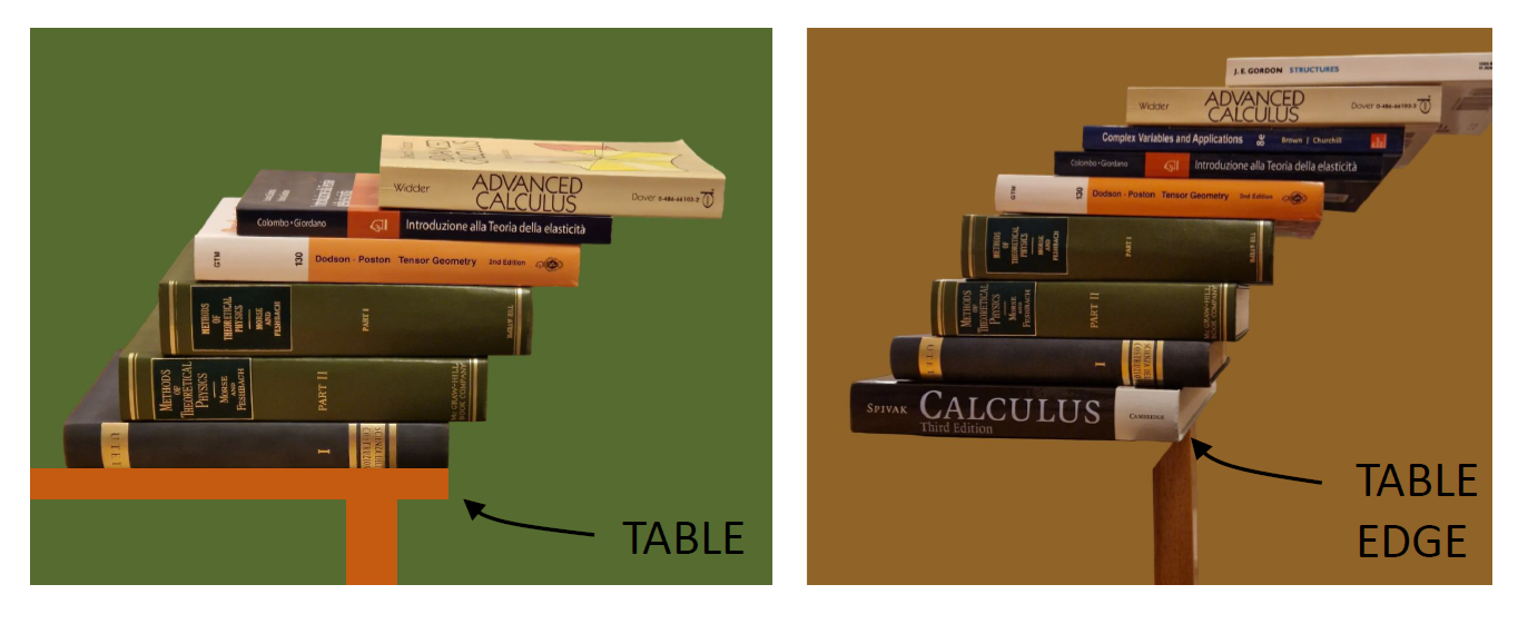
It is possible to stack the blocks on top of each other without using any glue, but we need to be a bit more careful because things are slightly different. A vaguely related scenario is illustrated in the photographs seen below (using books rather than wooden blocks; also, the offset distance is not the same for all books because the aim was to obtain a maximum overhang – more about this in a future post).
